Category Archives: Sensor

Printed/Flexible Sensors Required for Wearable Skin Patches

Publisher: Printed Electronics World
Publication date: 2020.12.14
Summarized by Inyeol Yun

–Introduction
v. Wearable technology with sensing functionality is emerging as a highly promising application for printed/flexible electronics.
v. Deployed either as skin patch or embedded within an e-textile, these devices enable parameters such as heart rate and temperature to be recorded in real-time and then transmitted wirelessly.
v. With such clear benefits, IDTechEx estimate that the wearable skin patch market for healthcare applications will reach around $4 bn by 2030.

<Figure 1>

–Need for continuous monitoring
v. A major trend in the healthcare sector is a shift towards continuous monitoring
v. Benefit 1: rather than attending a doctor’s surgery or hospital for a check-up, the patient can remain at home. (The current COVID-19 situation has emphasized this benefit since patients can have their temperature measured remotely without having to interact with healthcare professionals and thus risk transmitting or acquiring the virus.)
v. Benefit 2: continuous monitoring enables data to be acquired with a far higher temporal resolution than would be possible with in-person visits since a skin patch can be worn at all times. This additional data, coupled with analysis via machine learning, should facilitate improved diagnosis and preventative medicine.

<Figure 2>

–Monitoring electrical signals
v. Electrocardiograms (ECG) for investigating the heart, electromyography (EMG) for recording electrical signals from muscles, and even detecting brain activity in epileptic patients.
v. Electrode: Ag/AgCl, conductive ink with wave-like pattern.

–Pressure and strain sensing
v. Example 1: incorporating a conformal thin film piezoresistive sensor can continuously measure the pressure being applied by bandages and alert medical staff if the bandage needs adjusting.
v. Example 2: monitoring joint movement using printed capacitive strain sensors incorporated, for example, into knee and elbow sleeves. This is useful for those receiving physiotherapy since the amount and extent of movement can be continuously assessed.

–Wound monitoring
v. At present, the only way to check a wound is to remove the dressing – by integrating sensors and electronics, the healing process can be monitored in real-time without the dressing being removed.
v. This sensing can involve measurement of temperature and pH, ideally with spatial resolution to monitor how healing is progressing.

–Flexible hybrid electronics
v. At present most of the electronics for signal processing and communication used in wearable skin patches and e-textiles are contained within a rigid plastic box. While this provides protection and is required to enclose a conventional rigid PCB, it adds bulk and makes the patch or clothing uncomfortable to wear.
v. As such, much effort is being devoted to placing as much of the electronics as possible onto the stretchable substrate, rather than using a rigid PCB. This approach is termed flexible hybrid electronics (FHE), which is an emerging manufacturing methodology that utilizes the best aspects of conventional and printed/flexible electronics.
v. IDTechEx forecast that across all applications FHE will be around a $3.2 bn market by 2030.

Decoding of Facial Strains via Conformable Piezoelectric Interfaces

Author: Tao Sun, Canan Dagdeviren* et al.
Affiliation: Massachusetts Institute of Technology, USA
Journal: nature biomedical engineering
Publication date: 2020. 10. 22
Summarized by Jeung Jinpyeo

-Motivation
v. Human skin allows for an abundance of fine muscular movements that form the ability to communicate in daily life
v. Patients with amyotrophic lateral sclerosis (ALS) or related disorders experience barriers to tasks that require finger dexterity and sustained speech, but often retain the ability to form facial motions
v. Methods for in vivo characterization of facial deformations often involve EMG or camera tracking
v. Require cumbersome computational load or use of rigid, bulky structures which presents a difficulty for continuous use in daily life

-Use of thin film piezoelectric materials
v. Representative materials: lead ziconate titanate (PZT), BaTiO3 and Zinc oxide (ZnO), etc
v. Convert changes in soft tissue strain to measureable changes in electrical voltage and current
v. Advantages: 1) High dynamic sensitivity across a wide pressure regime (0-100 kPa), 2) Simplicity in device structure, 3) Reliability, 4) Stability under cyclic loading conditions
v. Widely deployable system necessitate: 1) Use of low-cost materials, 2) easily manufacturable processes, 3) testing and validation

-Conformable facial code extrapolation sensor (cFaCES) (Fig. 1)
v. Robust, mechanically adaptive, visually invisible in vivo monitoring devices
v. Aluminum nitride (AlN) piezoelectric thin films on compliant PDMS substrates
v. AlN fabricated in a 200-mm wafer process results in a low-cost (US $10 per cFaCES) disposable device and also lead-free material
v. Mo electrodes: 1) Reduced lattice mismatch, 2) good adhesion with AlN layer, 3) low cost
v. Fabrication process (Fig. 2)
v. AlN layer is formed by reactive sputtering process (nitrogen plasma reaction with Al)
v. Capacitor-type elements (diameter: 0.48 cm)
v. Neutral mechanical plane (Fig. 3)

<Figure. 1>

<Figure. 2>

<Figure. 3>

-Calibration with three-dimensional digital image correlation (3D-DIC) (Fig. 4)
v. Optical measurement of strain by 3D-DIC and electrical measurement of strain by cFaCES (Fig. 5)
v. Sensor placement for analysis of skin strains (Fig. 6)
v. Real-time decoding (RTD) and classification of facial motions (Fig. 7)
v. Dynamic warping and k-nearest neighbours (kNN-DTW) model are used

<Figure. 4>

<Figure. 5>

<Figure. 6>

<Figure. 7>

Self healable neuromorphic memtransistor elements for decentralized sensory signal processing in robotics

Journal: nature communications
Author: Rohit Abraham John and Naveen Tiwari
Affiliation: School of Materials Science and Engineering, Nanyang Technological University
Publication date: 2020.8.12
Summarized by Yunsik

– Introduction
v. Tactile sensor is necessary to robot system for avoiding obstacles and handling physical contact
v. Current robotic systems with tactile sensors are primarily managed by central systems with remote embedded sensors
v. These systems are limited in the amount and sensitivity of the sensor due to problems such as bandwidth and speed of remote communication
v. In addition, serial communication between the sensor and the control unit will limit the number of sensors available

– Contents
v. Decentralized neuromorphic decisionmaking concept to lower the temporal redundancy of event-based sensory signals and vastly reduce the amount of data shuttled to the central processing system, hence lowering the latency and wiring demands
v. Satellite Threshold Adjusting Receptors (STARs) impremeted Nociception
v. Satellite weight adjusting resistive memories(SWARMs) and CMOS satellite spiking neurons (SSNs) implemented synapses and neurons
v. STARs and SWARMs consist of Indium-tungstem oxide(IWO) memtransistors with self-healing ionic dielectrics

Fig. 1 Concept illustration of centralized and decentralized intelligence in robotics.

Fig. 2 (a) IWO Transistor with ionic dielectrics. (d and a) Transistor hysterisis. (c) Switching mechanism of Satellite Weight Adjusting Resistive Memories

Fig. 3 Nociceptive characteristics of satellite threshold adjusting receptors (STARs).

Fig. 4 Biological and artificial neural network. Relative timing between pre- and postsynaptic spikes create voltage differences across synapses/satellite weight adjusting resistive memories (SWARMs), tuning the firing rate of neurons/satellite spiking neurons (SSNs). In the proposed approach, teacher signals from the nociceptor/STAR modulates the synaptic weights creating association.

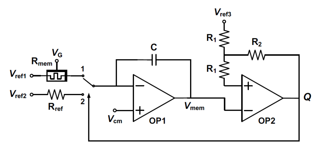
Fig. 5 Satellite Spiking Neuron (SSN) Circuit.

Fig. 6 Weight changes in the SWARM follow an anti-Hebbian spike-timing-dependent plasticity (STDP) rule. Representative raw I–t curves of long-term potentiation (LTP) and depression (LTD) are shown.

Fig. 7 Associative learning of pain and texture signals using satellite threshold adjusting receptors (STARs) and SWARMs. Four SWARMs are trained with signals related to the texture of objects and noxious output signals from STARs.

Fig. 8 The ionic liquid inclusions trigger the healing process by improving the thermal mobility of the polymer housing via a plasticizingmechanism

Fig. 9 Demonstration of the working of decentralized memristive neuromorphic elements for robotics.

Heterogeneous integration of rigid, soft, and liquid materials for self-healable, recyclable, and reconfigurable wearable electronics

Journal: Science Advances 2020
Author: Chuanqian Shi, Jianliang Xiao et al.
Affiliation: School of Aerospace Engineering and Applied Mechanics, Tongji University, Shanghai, China.
Publication date: 2020. 11.06
Summarized by Jueun Kim

-Summary
v. Demonstrated a highly stretchable, self-healable and wearable electronics system that can provide physical motion tracking, body temperature monitoring, and sensing of acoustic and ECG signals.

-Introduction
v. Heterogeneous integration of rigid(chip components), soft(thermoset polyimine), and liquid(eutectic LM) materials.
v. Elastomeric polyimine
: Substrate
Encapsulates chip components
v. LM(liquid metal)
: provides excellent electrical conductivity (3.4×10⁶ S/m) and superior mechanical softness and deformability
Interconnection between chips

-Fabrication
v. Multilayer construction and optical images of the multifunctional wearable electronics(Fig.2)

  • Synthesize polyimine(covalent bonding)
    : Terephthalaldehyde, diamino-N-methyldipropylamin and tris-amine were mixed in methanol (Fig.1)
  • Evaporating methanol in a fume hood for 12 hours, heat pressing (80°C 8.5kPa for 12hours) -> Covalent bonding=Imine reaction
  • 0.2-mm-thick Silicon paper mask onto a polyimine film substrate
  • Screen printing method to brush EGaIn(Ga:75%, In:25%, Sigma-Aldrich) LM using razor blade
  • Solidification LM below 15.7°C
  • Peeling off the mask (Patterning done)
  • Chip components are located
  • Applying polyimine and curing solution onto the device(encapsulation and protection to the LM circuitry and chip components.

< Figure 1 >

< Figure 2 >

-Result
v. The multifunctional wearable electronics (Fig.3)
:1) ECG sensor 2) Thermometer sensor (body temperature) 3) Accelerometer or motion sensing

< Figure 3 >

v. Stretchability of the multifunctional wearable electronics
: ECG data of the same device under different deformation modes. (Fig.4)

< Figure 4 >

v. Self-healing of the multifunctional wearable electronics

  • To heal the broken polyimine device, a 1-kg weight was used to press polyimine for 13min at RT(Fig.5)
  • Pressing is used to improve interfacial contact and to accelerate bond exchange reactions for more effective interfacial healing.
  • The EGC data during cutting and self-healing and EGC data when the device is stretched by 60% after self-healing 48 hours. (Fig.6)

< Figure 5 >

< Figure 6 >

v. Recyclable of the multifunctional wearable electronics
-When electronics is severely damaged or no longer needed, it can be fully dissolved in methanol, and chip components can be separated and reused.(Fig.7)

< Figure 7 >

-Conclusion
v. Highly stretchable (uniaxially by 60%, biaxially by 30%), self-healable and multifunctional wearable electronic system
v. Low cost method to use liquid-metal material
v. Recyclable  Can benefit the sustainability, economy of our society

Wearable Biofeedback System to Induce Desired Walking Speed in Overground Gait Training

Journal: MDPI Sensors
Author: Huanghe Zhang and Yefei Yin et al
Affiliation: Department of Mechanical Engineering, Stevens Institute of Technology, Hoboken
Publication date: 2020.6.18
Summarized by Yunsik

– Introduction
v. Decreased walking speed is associated with fear of falling, and increased stride-to-stride (STS) variability in walking speed is a predictor of future falls in the elderly
v. Walking speed may also serve as an effective screening parameter for frailty in the elderly and as an indicator of neurological or musculoskeletal disorders

– Wearable biofeedback systems (WBS)
v. A new, minimally obtrusive WBS and (ii) a new closed-loop vibrotactile stimulation method to induce a desired walking speed in the wearer during overground walking tasks.
v. The WBS, built upon our previous work on instrumented footwear, is capable of measuring the stride velocity and phase of the gait cycle in real-time during overground walking tasks.
v. The results indicated that the proposed closed-loop vibrotactile stimulation method could induce more accurate gait speed adaptations compared to conventional fixed-tempo (open-loop) stimulation and also preserve the natural variability of a person’s gait

Figure 1. (a) The proposed wearable biofeedback system (WBS) consists of two insole modules, a data logger, and a vibration-control unit; (b) The insole module includes a multi-cell piezo-resistive sensor, an IMU, and four eccentric rotating mass (ERM) motors, all embedded in the insole; (c) The vibration-control unit includes a control board and a Li-Po battery. The instrumented insoles are fitted inside regular sneakers; the logic unit is housed inside a customized 3D-printed enclosure and attached to the wearer’s shoes with a clip; and the vibration-control unit is attached to the user’s distal shank through Velcro straps.

Figure 2. System architecture.

Figure 3. Flowchart of closed-loop vibrotactile control. θp is the measured foot pitch angle, and a isthe foot acceleration. SVh, SLh, and STh are the real-time stride-to-stride estimates of stride velocity,stride length, and stride time, respectively. SVT represents the target walking speed. φh and φWBSare the user’s current gait phase and target phase, espectively. ∆φdis the target phase difference.IC, initial contact; FF, foot-flat; TO, toe-off; AFO, adaptive frequency oscillator

Figure 4. Effects of the closed-loop stimulation on the gait of a representative participant. The black line represents the normalized ground reaction force (GRF) extracted from the multi-cell piezo-resistive sensor. If the user’s current walking speed (SVh) is slower than the target speed (SVT) set by the experimenter, the stimuli anticipate the IC to encourage a faster pace (a); Conversely, if SVh is faster than SVT, the stimuli lag the IC, to elicit a slower pace (b).

Figure 5. (a) Experimental protocol. The sequence of the two rhythmic stimuli (OS = open-loop vibrotactile stimuli, CS = closed-loop vibrotactile stimuli) was randomized. The stimuli in OS mode were triggered at a constant pace corresponding to a target cadence CADT, while the stimuli in CS mode were modulated by the PI controller, given a target velocity SVT

Figure 8. (a,b) Group averages of the percentage mean absolute errors (MAE%) of SV and CAD induced by the two stimulation methods, OS and CS, during S2. MAE% values are computed with respect to the target values SVT and CADT; (c,d) Coefficient of variation (CV) of SV and CAD induced by the two stimulation methods during S2.

Figure 9. (a,b) SVh for a representative participant for the two stimulation methods, OS and CS, during S3. The black vertical line represents the time at which the stimulation engine was activated during the walking task; (c) Group averages of the percentage mean absolute errors (MAE%) of SV induced by OS and CS during S3. MAE% values are computed with respect to the time-varying target values SVT(t).

Figure 10. (a,b) CADh for a representative participant for the two stimulation methods, OS and CS, during S3. The black vertical line represents the time at which the stimulation engine was activated; (c) Group averages of the percentage mean absolute errors (MAE%) of CAD induced by OS and CS during S3. MAE% values are computed with respect to the time-varying target values CADT(t).

Near–hysteresis-free soft tactile electronic skins for wearables and reliable machine learning

Journal: PNAS
Author: Haicheng Yao, Benjamin C. K. Tee et al.
Affiliation: Nation University of Singapore, Singapore
Publication date: 2020.09.28
Summarized by Jeung Jinpyeo

– Motivation
v. Soft-elastomer-based electronic skin generally possess hysteresis problems
v. Irreversible frictional energy dissipation of polymer chains in the viscoelastic elastomers during cyclic deformation
v. Conductive polymer or piezoresistive polymer are highly sensitive, but generally face severe hysteresis
v. The paper present a pizoresistvie pressure sensor with high sensitivity and low hysteresis

– Tactile Resistive Annularly Cracked E-Skin (TRACE) (Fig. 1)
v. PDMS micropyramids
v. Soft indentation process (Fig. 2)
v. Each pristine Pt-coated micropyramid was indented into soft layer by a small compressive force
v. Reconnection of neighboring metal-film segments
v. Increased contact area between electrodes and micropyramids

<Figure 1>

<Figure 2>

– Sensor performance (Fig. 3)
v. TRACE sensor exhibited a higher sensitivity over a broad pressure range (0-20 kPa)
v. Sensitivity: differentiating resistance-pressure curve
v. Degree of electromechanical hysteresis (DHe): The ratio of area difference between loading and unloading cycle of the resistance-pressure curve
v. Excellent characteristics

<Figure 3>

– Applications
v. Artery pulse measurement (Fig. 4)
v. High-density pressure distribution mapping on a robotic hand (Fig. 5)
v. Texture classification using deep learning (Fig. 6)

<Figure 4>

<Figure 5>

<Figure 6>

An epicardial bioelectronic patch made from soft rubbery materials and capable of spatiotemporal mapping of electrophysiological activity

Journal: Nature Electronics
Authors: Kyoseung Sim and Cunjiang Yu et al.
Affiliation: University of Houston (USA)
Publication date: 2020.11.03
Summarized by Inyeol Yun

– Introduction
v. An epicardial bioelectronic patch for investigating and treating heart diseases.
v. The patch is made from materials matching the mechanical softness of heart tissue and can perform spatiotemporal mapping of electrophysiological activity, as well as strain and temperature sensing.
v. The patch can provide therapeutic capabilities (electrical pacing and thermal ablation), and a rubbery mechanoelectrical transducer can harvest energy from heart beats.

<Figure 1>

– Methods
v. Double-sided AgNWs/PDMS electrode. (Fig. 2)
v. Multifunctional rubbery epicardial bioelectronic patch. (Fig. 3)

<Figure 2>

<Figure 3>

– Results
v. Result of each function (fabricated on PDMS substrate).
v. Transistor validation.
v. Spatiotemporal mapping results.
v. In vivo validation of physical sensors for ablation and harvesting.

<Figure4>

<Figure 5>

<Figure 6>

<Figure 7>

Accurate Spirometry with Integrated Barometric Sensors in Face-Worn Garments

Journal: MDPI Sensors
Author: Bo Zhou et al
Affiliation: German Research Center for Artificial Intelligence
Publication date: 2020.6.29
Summarized by Yunsik

– Introduction
v. To date, breathing volume measurement is mostly restricted to constrained laboratory settings due to the form factor of existing spirometers
v. The airflow, spirometers typically require directing all the air flow from the patient to a sensing element
v. Such measurement modalities prevent miniaturizing spirometers, because if the vent cross-section area is too small, the user’s breathing will be restricted

– Novelty
v. We demonstrate the possibility of performing accurate transient breathing volume measurement in a wearable garment in the form of a sports mask, as opposed to hand-held novel spirometers, which mostly require a specific structure with a breathing tube
v. The only sensing element needed is a pair of low-cost (three Euros) miniaturized (2.5 millimeters) barometric pressure sensors
v. The approach is made possible by shifting the measurement modality, from directly placing sensors in the airflow duct to elaborating the pressure difference of the inside and outside of the face mask compartment

Figure 1. Sensing modality comparisons between current typical mobile spirometers and our approach. (a) Pneumotachometer-type and (b) turbine-type spirometers all require mechanical parts that cover The entire airway; (c) our approach only requires millimeter-scale barometric sensors on a normal facial mask and does not require The entire airway.

Figure 2. Flow-volume loop of a FVC maneuver from Participant 1.

Figure 3. The airflow and air volume of three consecutive FVC maneuvers, with normal tidal breathing in between. The spirometer’s signals are the original measurement; the barometer’s values are predicted with The inclusive-poly5 model.

Figure 4. The hardware and communication structure during the experiment: outside view (a) and inside view (b) of the facemask.

Figure 5. (Left) a participant performing a standard clinical forced vital capacity (FVC) test. (Center) a participant performing the FVC test with the calibration system. (Right) our proposed smart mask functions without extra instrument. Note that our instrument is fully integrated with a standard sports mask routinely used by athletes to control air inflow during exercise without making the mask in any way more obtrusive.

Figure 6. Calibration setup of The BME280 sensor for spirometry: (a) M2S setup, (b) S2S setup.

Figure 7. Flowchart of The major evaluation steps.

Figure 8. Linear fitting with The root models (a), polynomial curves (b) and neural network (c) regression fitting on The data from all participants combined.

Electronic‐ECM: A Permeable Microporous Elastomer for an Advanced Bio‐Integrated Continuous Sensing Platform

Journal: Advanced Materials Technologies
Author: Matthew S. Brown et al
Affiliation: State University of New York at Binghamton (USA)
Publication date: 2020.5.25
Summarized by Yunsik

– Introduction
v. Electrospinning has emerged as a superior fabrication technique to produce nano- to micro- fiber diameter materials due to its low cost, simplicity, and controllable processing parameters
v. Previously developed electrospinning technique has disadvantages on fabrication procedure and material

– electronic-extracellular matrix (e-ECM)
v. Presented work introduces the development of a 3D elasomeric mesh constituting of PDMS, possessing comparable mechanics to the epidermis with a permeable network for water, gas, and small molecule diffusion while remaining capable of irreversible silane bonding for soft electronics
v. Mechanical properties of fibrous elastomer differ in base to cure ratio and wetting
v. Fabrication

v. In vitro biocompatibility of skin kerinocyte cells (HaCaT) on PDMS substrates was assessed on both day 3 and 7 utilizing a live/dead assay

Figure 1. Electronic-extracellular matrix (e-ECM) for chronic, inflammation-free, soft bioelectronics. Schematic illustration of current epidermalelectronics (left). Cross sectional view of conventional epidermal electronics, establishing debilitations in heat, fluid, and gas permeation (right).B) Schematic illustration of ultrathin, porous, e-ECM device (left). Cross sectional view of a porous device facilitating passive mass transfer of sweat,heat, and gas (right). C) Image of e-ECM device laminated on skin in a moist environment. D) SEM image of fibrous PDMS laminated on skin, highconformability within skin groves (scale bar, 20 μm).

Figure 2. Coaxial electrospinning fabrication and analysis of 30:1 fibers. A) Coaxial electrospinning set up. B) Taylor cone formation from coaxial needle. PVP enveloping the PDMS core and the formation of a PDMS-PVP coaxial jet. C) Core-sheath structure of nanofibers. D) Confocal image fluorescent staining of core-sheath structure (PDMS-blue, PVP-red; scale bar, 5 μm). E) Image of bulk fiber mat (scale bar, 1 μm). SEM image of: F) PDMS-PVP fibers (scale bar, 20 μm), G) PDMS-PVP cross section (scale bar, 3 μm), and H) PDMS fibers after removing sheath in ethanol (scale bar, 20 μm). I) AFM analysis of PDMS fibers. Surface characterization with EDS analysis of J) PDMS-PVP fibers and K) PDMS fibers. L) FTIR spectrum of PDMSPVP fibers and PDMS fibers.

Figure 3. Physical and mechanical characteristics of PDMS fibers. A) Stress and strain curves of 30:1 PDMS fibers: in ambient (blue) and wet conditions (black). B) Elastic modulus of PDMS fibers at different base to cure ratios. Epidermal elastic modulus range (10–500 kPa).[14] C) Experimental and D) FEA deformation response of 30:1 fibers. SEM image of the 30:1 micromesh at different strain rates: E) 25%, F) 50%, and G) 100% (scale bar, 10 μm). H) Water vapor permeability of the micromesh (10:1 and 30:1 fibers) versus blank and 30:1 film (*p < 0.0125; Bonferroni correction, Games– Howell). I) Optical transmittance of 30:1 PDMS fibers mounted on glass. J) Adhesion strength of common elastomeric substrates versus 30:1 fibers.[27] K) Experimental set up of the adhesion test with a force gauge (Mark-10, USA). L) Demonstration of delamination of the substrate to the skin. M) Device detachment from the skin.

Figure 4. Biocompatibility of elastomeric fibers. A) Confocal imaging of live/dead stained HaCaT cells cultured for 3 and 7 days (scale bar, 100 μm). B) Z-stack of cells cultured on 30:1 fibers for 7 days. C) SEM image of 30:1 fibers at day 7 (scale bar, 20 μm). D) Relative fluorescence intensity of cells cultured at day 3 and 7.

Figure 5. Application of a fully fluid permeable device. A) Microscope image of electrode on silicon wafer (scale bar, 2 mm). B) The device under relaxation, stretching, pinching, and twisting. C) SEM image of electrode laminated on fibers (scale bar, 4 μm). D) Electrode placement on wrist for e-ECM and commercial electrode. E) Commercial electrode ECG response compared to e-ECM device. F) Experimental design. G) Schematic illustration of electrode placement sites: right chest (N-negative), left chest (P-positive), and left upper quadrant (G-ground). ECG measurement of e-ECM device H) before and I) after exercise. ECG measurement of film device J) before and K) after exercise

Moisture-insensitive, self-powered paper-based flexible electronics

Journal: Nano Energy
Authors: de Medeiros, Marina Sala, Daniela Chanci, and Ramses V. Martinez
Affiliation: Purdue University
Publication Date: 2020.08.16
Summarized by Gilsu Jeon

-Introduction
v. Music player interface on a flexible paper
link: https://www.youtube.com/watch?v=c9E6vXYtIw0&feature=emb_logo
v. Self-powered, eco-friendly paper based electronics technology is needed.
v. Papers are moisture sensitive and absorbs solvents, leading to ink spread.
v. Piezo-electric based energy harvesting system is too costly.
v. Cost-effective, moisture-insensitive, self-powered paper based electronics is achieved
RF-SPEs: sequential spray-deposition of alkylated organosilanes, ethyl cellulose, Ni nanoparticles, and polytetra-fluoroethylene (PTFE, Teflon)

-Experiments
v. Fabrication of RF-SPEs on a single sheet of paper

<Figure 1> Fabrication process of RF-SPEs

1) Spraying a fluoro-alkylated silane solution to make paper surface omniphobic.
2) Sequential deposition of PTFE, NiNPs (with IPA solvent), ethyl cellulose, NiNPs, and fluoro-alkylated silane with stencil mask for patterning (10 um-thick each).
3) Mask removal and inkjet printing on the opposite side of the paper.

-Results
v. Resistance to fold damage

<Figure 3> Resistance change in NiNPs ink pattern with folding cycles

v. Surface & Electrical property depending on fluorination, alkyl-chain length of organosilane, and type of papers.

Paper information:
Copy paper (2.0 ± 0.5μm), Whatman#50 (3.3 ± 0.8μm)
Whatman#1 (6.4 ± 1.2μm), and Blot (9.6 ± 1.6μm)

<Figure 4> Contact angle with water with various paper & organosilane conditions

<Figure 5> Electrical output from RF-SPEs in 6.25cm2 tribo-responsive area

v. RF-SPEs with SSHI (Optimized: Whatman#1 with C12F)

<Figure 6> Synchronized switch harvesting on inductor (SSHI)

v. Rectified by SSHI, and sent to paper-mounted microcontroller (Bluefriut; Adafriut Inc.)

<Figure 7> Open circuit voltage & Short circuit current after rectifying process

-Flexible paper-based electronics applications
v. Keypad

<Figure 8> Paper keypad with good flexibility and resistance to contamination

v. Interactive Music player

<Figure 9> Interactive music player

-Conclusion
v. Self-powered, flexible electronics on paper could be achieved
v. Omniphobic surface, high resistance to damage & contamination
v. Sufficient electrical output for user interface